
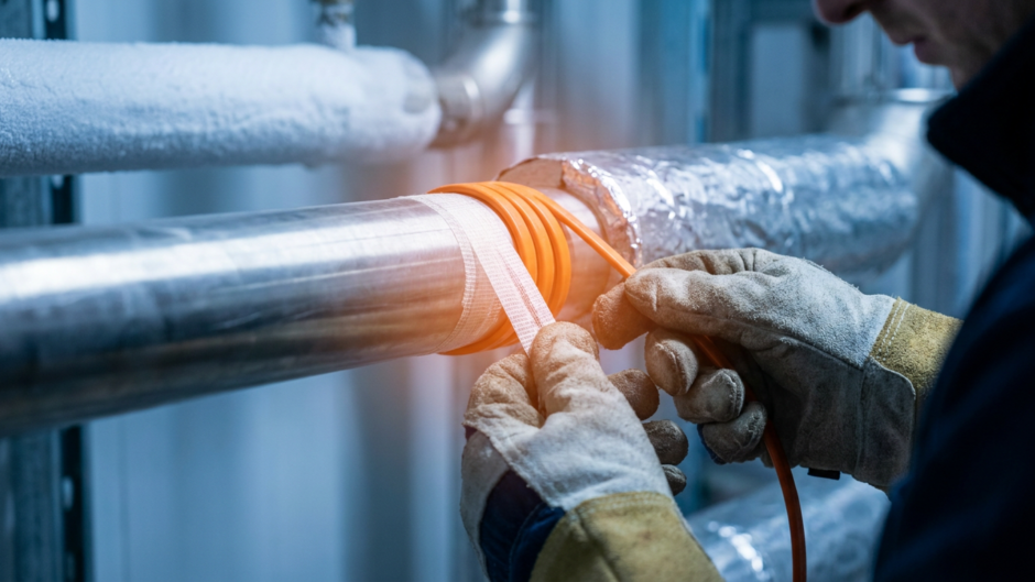
5 Common Mistakes to Avoid When Installing Pipe Heat Tracing
A heat tracing design still depends on careful installation. The cable, controls and insulation have to work together under the conditions specified for the job. Shortcuts can leave problems hidden until temperatures drop, when repairs are harder to arrange. These five areas deserve a deliberate check before the system is put into service, rather than an assumption that getting the cable onto the pipe is enough.
Mistake 1: choosing the wrong cable type
Grabbing whatever heating cable is on the shelf feels like a shortcut, but cable types are not interchangeable. Constant wattage and self-regulating products have different operating characteristics. Don’t assume that crossing or overlapping a cable is permitted just because another product allowed it. Check the instructions for the exact cable selected and use the approved layout for that application.
Match the cable to the job before you buy anything. Pipe material, process temperature and hazardous area suitability all need checking against the design. When considering products from heat-trace.com/, use the relevant specification and installation sheets rather than treating heat trace like generic electrical wire. Confirm the product is suitable for the application instead of relying on its name alone.
Mistake 2: skipping the heat loss calculation
Don’t size a pipe heating system from a generic rule of thumb. Use the project’s heat loss calculation and the manufacturer’s design method. An undersized system may not maintain the required temperature; choosing more output without checking the design is not a reliable fix. The cable and controls need to suit both the heating requirement and the permitted temperatures of the pipe and system.
Check the pipe diameter, insulation type and thickness, required maintained temperature and design minimum ambient temperature. Make sure the calculation reflects what will actually be installed. If insulation or pipework changes on site, have the design reviewed before carrying on. A spreadsheet is only useful when its assumptions and method are appropriate to the job, so don’t confuse a quick calculation with a checked one.
Mistake 3: mounting the thermostat sensor wrong
Sensor position needs to match the control method. For pipe-temperature sensing, follow the specified contact position and separation from the heating cable. Don’t move that sensor into open air because it is easier to reach. Equally, don’t assume that every control system is designed to measure the pipe directly. Check the controller instructions and approved sensor layout before deciding where it belongs.
Make the position part of the installation check. Once the insulation is fitted, it is harder to see whether the sensor was installed as specified. If the drawing and the physical layout don’t agree, resolve that before covering the work.
Mistake 4: overtightening and overlapping the cable
Whether the design calls for spiral wrapping or a straight run, follow the product’s spacing, fixing and minimum bend-radius instructions. Pulling cable too tightly or forcing it around a fitting is not a substitute for the specified arrangement. Overlap rules depend on the cable and application, so don’t borrow them from a different installation.
Keep the actual installation sheet at hand. Check the route around elbows and supports as well as the easy straight sections. If there isn’t room for the approved layout, ask for the arrangement to be reviewed rather than improvising a tighter wrap.
Mistake 5: ignoring heat sinks
Valves, flanges and pipe supports need attention in the heating design. Don’t assume that an allowance for straight pipe covers every fitting along the run. Check the specified cable allowance and layout at each of these points before cutting or fixing anything in place.
Where the design calls for extra cable or a service loop, install it as shown. Packing spare cable into a small space is not the same thing. Also check that the arrangement leaves the fitting accessible for the maintenance the design anticipates, rather than discovering the conflict after the insulation goes on.
The step to remember: megger testing
Arrange the insulation resistance testing specified by the manufacturer, including the checks required before insulation covers the cable. Have a competent installer follow the prescribed test method and record the results. Visual inspection alone cannot establish that the cable’s electrical insulation is sound, and an insulation resistance test does not replace every other required check.
Treat damaged jackets, suspect terminations or unexpected readings as reasons to stop and investigate. Testing before covering the work makes faults easier to locate, but it isn’t the only stage at which the system may need checking. Follow the full inspection and commissioning sequence for the product.
Why installation discipline matters
Poor installation can undermine a carefully designed system. A failed heating circuit or an unprotected section of pipe may only become apparent when it is needed. Keep the cable selection, heat loss assumptions, sensor position, cable layout and fitting allowances tied to the approved design. Then check the finished installation and retain the test results. That is a more useful basis for dependable operation than a promise about how many winters it will last.